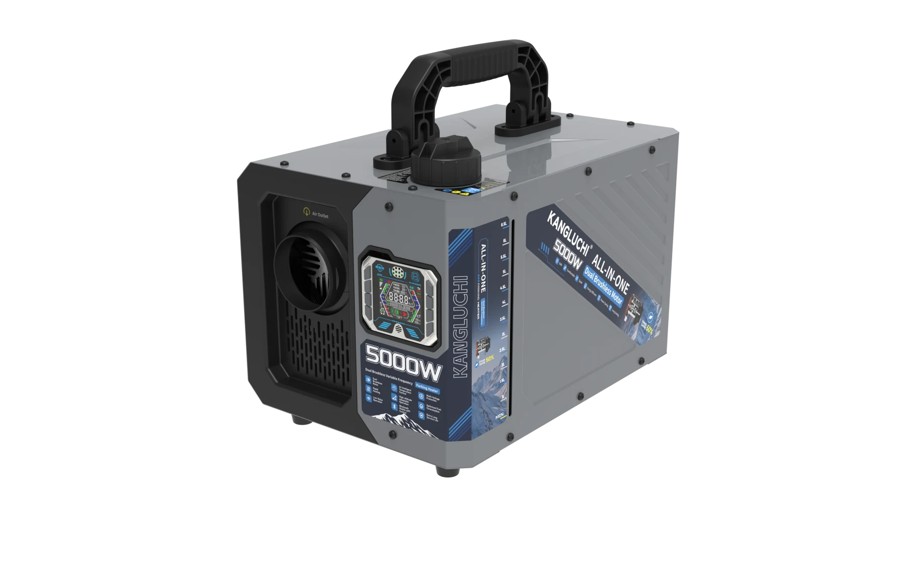
KANGLUCHI A1 All-in-One 5000W Portable Diesel Air Heater
Carbon monoxide hazard: route the exhaust outdoors and never run the heater in an enclosed, unventilated space. A CO alarm is strongly recommended. Read the full safety information.
Video guides
A1
A1 All-in-One installation guide
Installation video for the A1 all-in-one diesel air heater.
WARNING: Read all safety warnings, operating instructions, diagrams, and technical specifications supplied with this diesel air heater. Failure to follow them may result in electric shock, fire, and/or serious injury. Read the entire manual before use. Use the product only for its intended purpose; misuse may cause injury. Store it properly and inspect it for abnormalities before use. Stop using it immediately if any abnormality is found.
WARNING — toxic substances: Avoid contact with toxic substances. During installation/use, maintenance, and disposal, provide adequate ventilation space around the installed unit to prevent carbon monoxide poisoning. Route the exhaust outlet outdoors to prevent exhaust gases from entering the occupied space. Do not use the heater in an enclosed and/or unventilated area.
WARNING — flammable materials: Keep flammable materials away from the exhaust pipe during installation, use, maintenance, and disposal. The exhaust pipe becomes extremely hot during operation. Prevent fires caused by igniting flammable materials. Do not use the heater where flammable vapors or dust may be present, including fuel or carbon storage facilities, lumber warehouses, barns and similar locations, and diesel/gasoline filling stations. Keep it away from fuel tanks, compressed-gas cylinders, fire extinguishers, clothing, and other flammable items. Never use a lighter to start the unit. Turn off the heater before refueling.
Do not replace key components or use replacement parts made by other manufacturers without authorization. Follow all operating instructions and guidelines during installation and operation. Use only original accessories and replacement parts during installation and maintenance.
Do not disconnect the power supply during operation. Never stop the heater by disconnecting power while it is operating. If fuel leaks or spills from the fuel system, contact KANGLUCHI for service.
The unit stops heating when overtemperature protection activates. Do not disconnect power. Restart only after it has cooled naturally and the power has been turned off.
After turning off the unit, do not immediately disconnect power. Allow 3–10 minutes for the shutdown cooling cycle to finish and the unit to stop completely. The unit begins operating normally and producing heat 3–5 minutes after startup; wait patiently.
This unit may be used by children 8 years of age and older, persons with reduced physical, sensory, or mental capabilities, and persons lacking experience and knowledge, provided they have received instructions on safe use and fully understand the associated hazards. Children are strictly prohibited from operating the unit. Cleaning and user maintenance must be performed under guardian supervision; children must not perform these tasks alone.
Do not use the heater in spaces used to heat or transport hazardous materials. Follow all applicable regulations when installing the unit and operate it only in a well-ventilated area.
NOTICE: This signal word indicates a technical feature or possible product damage if the instruction is not followed.
What’s in the box
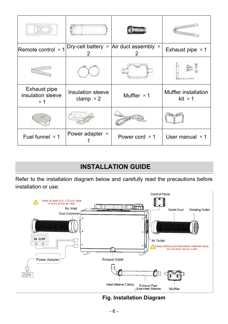
Remote control ×1
Dry-cell battery ×2
Air duct assembly ×2
Exhaust pipe ×1
Exhaust pipe insulation sleeve ×1
Insulation sleeve clamp ×2
Muffler ×1
Muffler installation kit ×1
Fuel funnel ×1
Power adapter ×1
Power cord ×1
User manual ×1
Included accessories (manual p.7)
Specifications
Parameter
PDF specification
Product Model
KANGLUCHI-A1
Heating Medium
Air
Operating Voltage
DC12-24V 10A (Adapter: AC100‑240V, 50/60Hz, 2.5A)
Rated Heat Output
5×(1±10%)KW
Rated Power
53W
Fuel Consumption
0.12L/h~0.39L/h
Fuel
Diesel
Fuel Tank Capacity
7L
Operating Temperature
-40℃~40℃
Operating Noise
≤75dB
Dimensions
390280300mm
Weight (excluding packaging)
Approx. 11.5kg
Weight (including packaging)
Approx. 13.4 kg
Installation
See manual p.7 above.
Refer to the installation diagram and read the precautions before installation or use. Suitable applications include RVs, boats, and tents. Never drill holes or install mechanical equipment on a wood floor. Side mounting is prohibited.
Install the exhaust pipe: if the heater is indoors, route the exhaust outdoors and insulate the pipe because its temperature may rise rapidly and create a fire hazard. If the heater is outdoors, extend the exhaust pipe to prevent exhaust gases from being drawn into the rear fan and entering the building, which could cause carbon monoxide poisoning. Keep the bottom exhaust pipe approximately 5 cm above the ground; take fire-prevention measures if it becomes excessively hot. Do not bend it excessively, as this may cause uneven exhaust flow. Do not install the flue exhaust pipe vertically upward; install it horizontally or with a downward slope. Keep the exhaust pipe unobstructed and its outlet away from flammable materials. Do not heat or ignite flammable items. Do not load goods on the ground.
Keep flammable materials away from the exhaust pipe and muffler hot-air outlet and use insulating material for protection. The exhaust pipe surface temperature is approximately 350°C. Do not use adhesives that do not meet high-temperature resistance requirements; they may produce odors and create a poisoning hazard. The installation guide also says to keep the bottom exhaust pipe 2 inches above the ground.
Install the air duct: leave 4 inches of clearance between the air inlets to ensure unobstructed airflow. The installation guide also says to leave 4 inches of clearance at the air inlet. Do not use an excessively long hot-air outlet duct; multiple bends may prevent heat from dissipating effectively and cause an overtemperature fault.
For hot-air outlet duct modification or extension, use ducting made of the same material or a high-temperature-resistant material. Keep its length within 2 meters and avoid sharp bends. For exhaust pipe modification or extension, use pipe made of the same material or high-temperature-resistant stainless steel. Keep its length within 2 meters, do not make sharp bends, and route it downward to discharge outdoors. Never make multiple upward bends. Do not use rubber seals with inadequate high-temperature resistance: they may produce odors and create a poisoning hazard.
Refuel only with diesel fuel that meets national standards; use only nationally approved safe fuel. Never use gasoline, alcohol, methanol, or other volatile fuels. Do not allow fuel to enter the housing: it may run down the inner wall into the heater and cause a fuel odor. Fill the tank until the fuel level is close to the fuel tank opening.
Use a power supply meeting these requirements: 12V, current ≥15A; 24V, current ≥10A. The unit may be powered directly by a power supply or battery. If using a battery, do not charge it while operating the heater. Insufficient current may cause malfunction. Ensure the battery connection is secure and reliable; securing it with clamps may result in poor contact.
When extending the power cable, use wire with a cross-sectional area greater than 2 mm². Wire that is too thin may provide insufficient current. After wiring, wrap all connections with electrical tape to prevent current leakage and fire hazards.
Never disconnect power while the heater is operating at high temperature. High temperatures may cause backfiring, and repeated power disconnection may cause permanent damage. If power is disconnected and you attempt to restart immediately, wait until all internal heat has dissipated before restarting.
First start-up
Before initial startup, fuel must reach the fuel inlet. Use Option A (recommended); if it does not succeed, use Option B.
Option A (recommended): automatic fuel priming
When starting for the first time, press “Settings” five times in succession. The system starts a 200-second fuel-priming mode and displays a countdown. During priming, it continuously monitors the fuel signal. When the glow plug detects fuel, the unit automatically ignites and starts. Press any button to stop early.
Option B: manual fuel pumping
The heater has a long fuel line. Before initial startup, manually pump fuel to the fuel inlet. Otherwise, after starting the unit, allow time for it to detect fuel; the system continuously monitors the fuel signal. Once the glow plug detects fuel, ignition and heating begin automatically.
Avoid over-priming
Pump fuel only until it reaches the fuel inlet, then stop. Excess fuel inside the unit prevents normal ignition and produces white smoke. If too much fuel has been pumped, disconnect the fuel line and restart the unit 2–3 times until normal operation is restored, then reconnect the fuel line. Alternatively, continuously blow air through the fuel inlet line with a hair dryer until the unit resumes normal operation.
Switch on
With the unit off, press and hold “On/Off” for 2 seconds. “Preheating” indicates that the unit has entered heating mode. At initial startup the default is Manual Mode, with level “5L” in Standard Mode.
Operating the heater
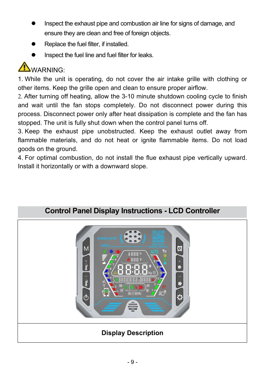
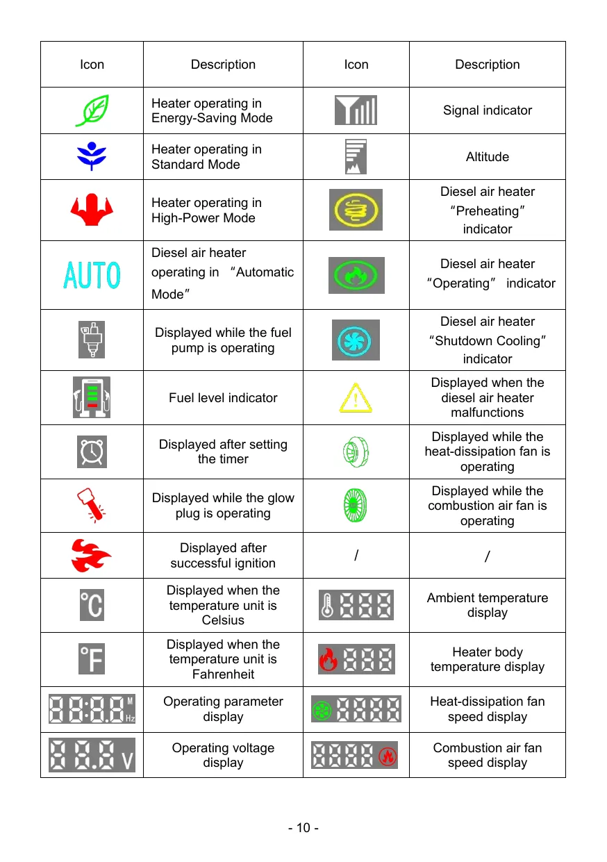
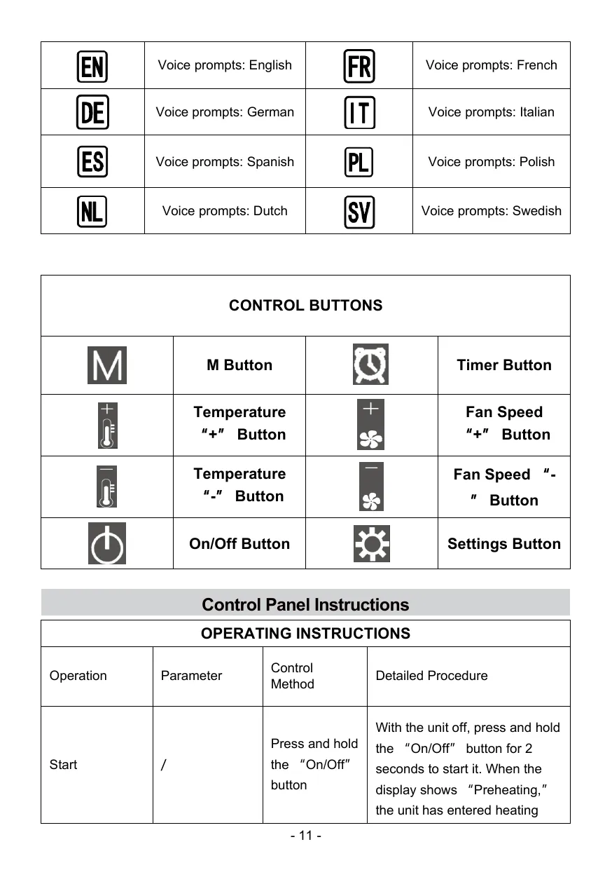
LCD display icons and control buttons (manual p.10, p.11, p.12)
The display shows Energy-Saving, Standard, High-Power, and Automatic modes; signal, altitude, preheating, operating, shutdown cooling, fuel pump, fuel level, malfunction, timer, heat-dissipation fan, glow plug, combustion air fan, successful ignition, Celsius/Fahrenheit, ambient and heater-body temperatures, operating parameters and voltage, and fan speeds. It also shows the selected voice-prompt language.
Start: With the unit off, hold “On/Off” for 2 seconds. The initial default is Manual Mode, “5L” in Standard Mode.
Shut down: While operating, hold “On/Off” for 2 seconds. The display shows “OFF,” then “Shutdown Cooling” until cooling completes and the unit shuts down. Do not operate the button during shutdown. NOTICE: Never disconnect power during shutdown. Otherwise internal heat cannot dissipate completely; restarting may produce a large amount of smoke, and insufficient cooling can damage the internal combustion air fan impeller. Allow combustion to finish completely before resuming normal operation. Disconnect power only after heat dissipation is complete and the fan has stopped; the unit is fully shut down when the control panel turns off.
Modes: Press “M” to cycle Boost → Standard → Energy-Saving → Automatic. Press “Fan Speed +” or “Fan Speed -” to adjust output: Energy-Saving 1–9L, Standard 4–9L, Boost 7–9L.
Automatic temperature: Default 21℃. Press “Temperature +” or “Temperature -” to set 10℃–45℃; the setting is stored in memory.
Parameters: While on, the output level is displayed by default. Press “Settings” to view fuel pump frequency → glow plug power → altitude → total operating time. Leave a parameter displayed for 20 seconds or press any button to return to the main screen.
Temperature unit: While on, hold “M” for 3 seconds to switch between Celsius and Fahrenheit (10–45℃ / 50–113℉). Leave the unit displayed for 5 seconds to confirm; the setting is retained after power is disconnected.
Operating time: Timing starts automatically after startup, up to 9999 minutes, then resets to zero. The value is not retained after power is disconnected.
Remote pairing: When power is first applied, press “Settings” three times to enter pairing mode; the display shows “315.” Press “Settings” on the remote to complete pairing. Effective range: ≤ 25 meters.
Timer: In standby, hold “Timer” for 2 seconds to set scheduled start. While operating, hold it for 2 seconds to set scheduled shutdown. Press “Fan Speed +” or “Fan Speed -” to select 5, 10, 20, or 30 minutes; each subsequent press changes the setting by 30 minutes, up to 24 hours. The displayed setting confirms after 5 seconds. Set it to 0 to cancel. The center colon flashes when enabled. For models with Bluetooth or 4G, the control-panel start/stop timer is unavailable; set it in the Chihuitong app, referring to the app for procedures and settings.
Voice announcements: Startup default is English. Hold “Settings” for 3 seconds, then press it to cycle English → French → German → Italian → Spanish → Polish → Dutch → Swedish. A language displayed for 5 seconds is confirmed and retained after power is disconnected. Announcements cover startup, shutdown, and fault-code status.
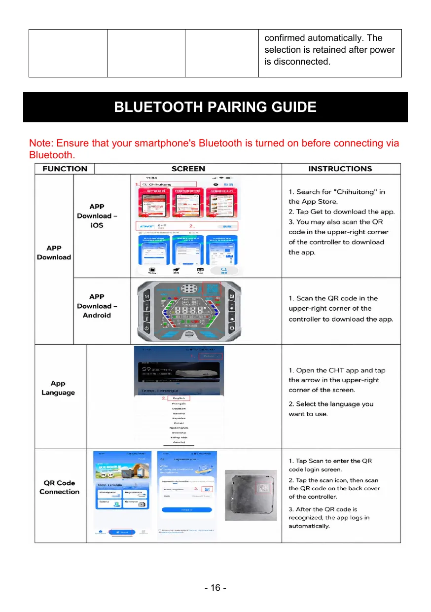
Bluetooth and app: Ensure the smartphone’s Bluetooth is turned on before connecting.
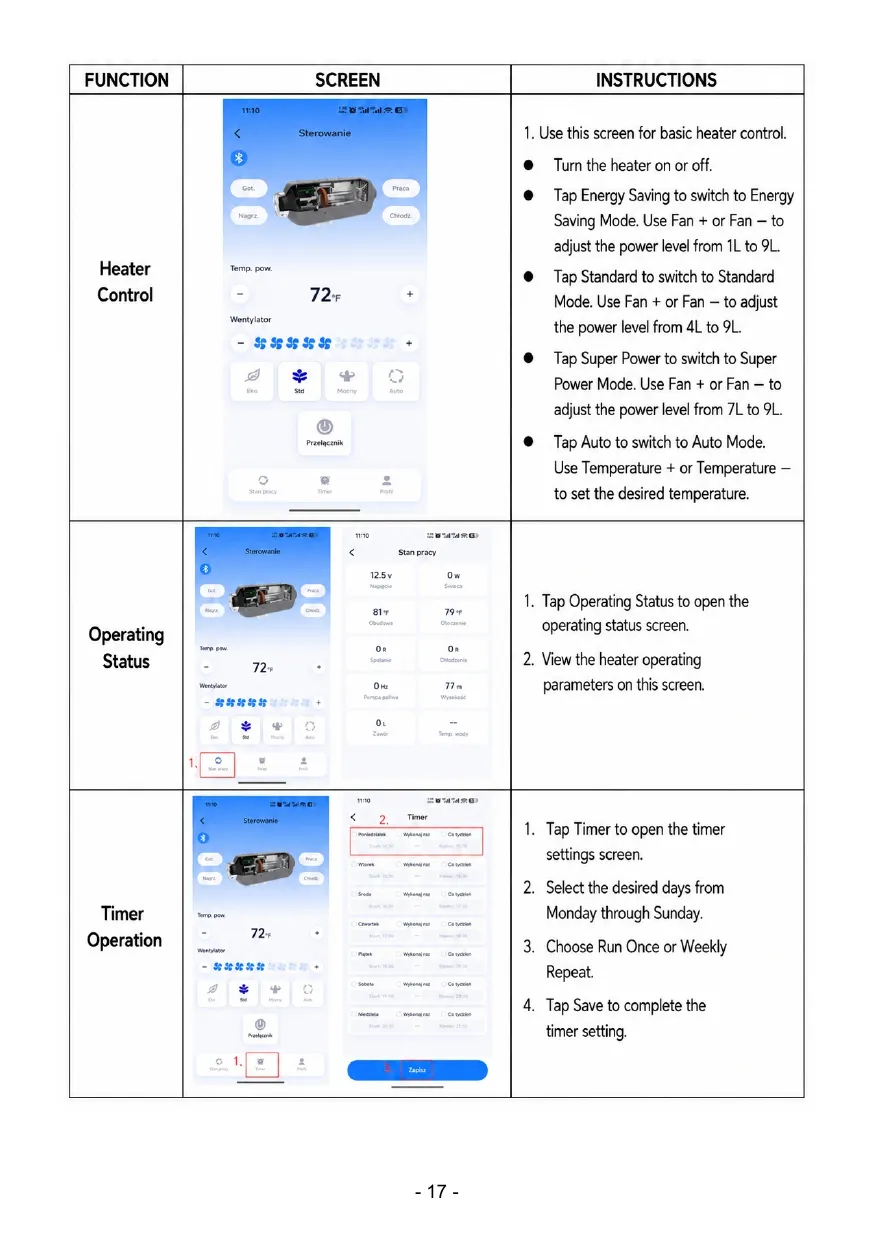
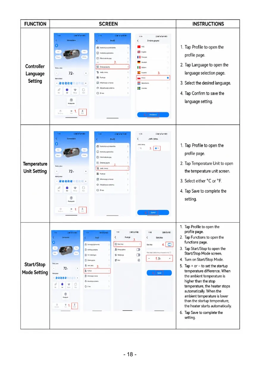
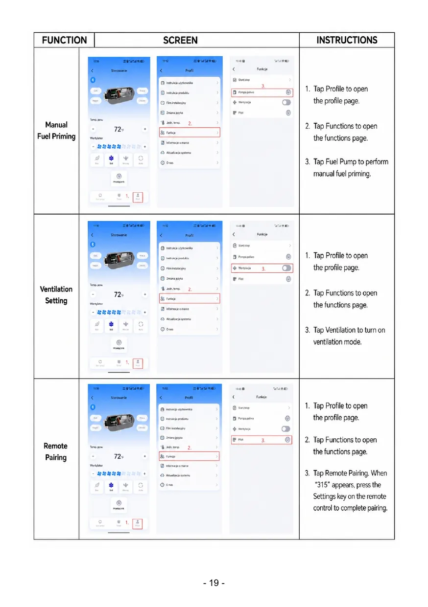
Bluetooth pairing guide and app screens (manual p.17, p.18, p.19, p.20)
Download: On iOS, search for “Chihuitong” in the App Store and tap Get; alternatively scan the QR code in the controller’s upper-right corner. On Android, scan that QR code to download the app.
App language: Open the CHT app, tap the arrow in the upper-right corner, and select the desired language.
QR code connection: Tap Scan to enter the QR code login screen. Tap the scan icon and scan the QR code on the controller’s back cover. After recognition, the app logs in automatically.
Heater control: Turn the heater on or off on the control screen. Tap Energy Saving and use Fan + or Fan − for 1L–9L; Standard for 4L–9L; Super Power for 7L–9L; or Auto and Temperature + or Temperature − to set the desired temperature.
Operating status: Tap Operating Status to open the screen and view heater operating parameters.
App timer: Tap Timer, select desired days Monday through Sunday, choose Run Once or Weekly Repeat, and tap Save.
Controller language: Tap Profile, then Language; select the desired language and tap Confirm.
Temperature unit: Tap Profile, then Temperature Unit; select °C or °F and tap Save.
Start/Stop mode: Tap Profile → Functions → Start/Stop. Turn on Start/Stop Mode, then tap + or − to set the startup temperature difference. When ambient temperature is higher than the stop temperature, the heater stops automatically; when it is lower than the startup temperature, it starts automatically. Tap Save.
Manual fuel priming: Tap Profile → Functions → Fuel Pump to perform manual priming. Follow the fuel precautions in First start-up.
Ventilation: Tap Profile → Functions → Ventilation to turn on ventilation mode.
Remote pairing: Tap Profile → Functions → Remote Pairing. When “315” appears, press the Settings key on the remote control to complete pairing.
1. Check the power supply and verify that voltage at the supply terminals is normal. 2. If above 32V, adjust the abnormal supply voltage. 3. If the supply is normal, replace the controller.
E02
Supply voltage too low
1. Check power: 12V/24V, ≥15A, ≥150W; minimum starting voltage ≥9V for 12V or ≥18V for 24V. 2. A power adapter, battery pack, converter, or similar device is recommended: 12V/24V, ≥15A, ≥150W. 3. Never use a fastening device to connect battery and wires because poor contact may cause failure. When extending the harness, select wire with a diameter of ≥2mm ² to prevent voltage drop and low voltage/current malfunction. If it still does not operate normally after extension, measure voltage and current separately at the supply and heater-harness ends.
E03
Fuel pump open circuit
1. Check the fuel pump connector for damage, loose terminals, and broken harness wires. 2. Check whether the pump plug is loose; disconnect and reinstall it to confirm. If none of these problems is found, replace the fuel pump.
E04
Fuel pump short circuit
1. Inspect pump wiring for insulation damage and shorts caused by pinching. 2. If there is no short circuit, replace the pump. 3. If that does not resolve it, replace the controller.
E05
Glow plug open circuit
1. Check that the connector is fully inserted and not loose. 2. If fully inserted, remove and inspect the glow plug for damage. 3. Replace it if damaged. 4. If normal, replace the controller.
E06
Glow plug short circuit
PDF code: E-06. 1. Inspect glow plug wiring for damaged insulation or crossed wires causing a short. 2. Carefully inspect the protective sleeves on the center and side electrodes at the base for damage that could cause a short. 3. If there is no short, inspect the glow plug for damage. 4. If normal, replace the controller.
E07
Abnormal heat-dissipation fan speed
1. Check that the unit is securely fastened and properly installed. 2. Check whether fan contact with the housing causes abnormal speed. 3. If not, replace the motor assembly.
E08
Heat-dissipation fan short circuit
1. Inspect fan wiring for insulation damage and shorts from pinching. 2. If insulation is intact, inspect the plastic housing and inside of the motor. 3. If no abnormality is found, replace the controller.
E09
Heater flameout
1. Check the fuel line for air and continuous fuel flow. 2. Inspect it for damage that could cause a leak. 3. Check whether the tank is low on fuel.
E10
Ignition failure
1. Check whether fuel is present in the fuel line. 2. If the heater is burning, inspect the sensor for damage and replace the sensor. 3. If it does not burn, repeatedly blow compressed air through the air intake and exhaust openings. Thoroughly clean the combustion chamber, then start again.
E11
Overtemperature warning
The temperature sensor detects whether the aluminum housing surface reaches or exceeds 295℃ and activates overtemperature protection. Carefully check whether the air inlet pipe, hot-air outlet pipe, or exhaust pipe is bent or excessively long; these conditions impair exhaust performance and prevent heat dissipation.
E12
Temperature sensor open circuit
1. Check that the sensor connector is fully inserted and not loose. 2. If fully inserted, inspect wiring for breaks. 3. If no problem is found, replace the sensor. 4. If the problem persists, replace the controller.
E13
Temperature sensor short circuit
1. Check sensor wiring for damaged insulation and short circuits. 2. If neither is present, replace the sensor. 3. If the problem persists, replace the controller.
E14
Communication lost
1. Check the control panel communication wire (blue wire) for damage. 2. Check for loose connector terminals. 3. If everything is normal, replace the control panel. 4. If the fault remains, replace the controller.
E15
Intake air temperature too high
Check ambient temperature around the control panel. If the code remains displayed when ambient temperature is below 65°C, replace the control panel.
E16
Abnormal combustion air fan speed
1. Check whether the impeller contacts the combustion chamber U-shaped rubber plug/asbestos gasket, preventing motor rotation or causing abnormal operation. 2. If the impeller is not obstructed, replace the motor assembly.
E17
Combustion air fan short circuit
1. Check wiring for pinched or damaged insulation that may cause a short. 2. If insulation is intact, inspect the plastic housing and inside of the motor. 3. If no abnormality is found, replace the controller.
E18
Combustion air fan open circuit
1. Check that the fan connector is fully inserted and secure. 2. If so, check the harness for broken wires. 3. If none are broken, replace the motor assembly. 4. If that does not resolve the problem, replace the controller.
E19
Heat-dissipation fan open circuit
1. Check that the fan connector is fully inserted and secure. 2. If so, check the harness for broken wires. 3. If none are broken, replace the motor assembly. 4. If that does not resolve the problem, replace the controller.
E20
Combustion air fan circuit fault
Replace the controller.
E21
Heat-dissipation fan circuit fault
Replace the controller.
White smoke from exhaust — unexpected power loss/excessive manual fuel pumping: Follow the excess-fuel procedure in First start-up. For unexpected power loss, while operating hold “Power” for 2 seconds; when “OFF” appears, shutdown begins. Never turn off the main power switch during shutdown cooling. Restarting before heat dissipates may produce smoke and damage the combustion air fan impeller. Wait until the fuel inside has burned completely before resuming normal operation.
Black smoke — insufficient oxygen or carbon buildup: 1. Check whether altitude is outside the calibrated parameter range; insufficient oxygen may cause ignition failure and black smoke. 2. Check the combustion air intake line for blockage. 3. Check whether limited space around the air inlet restricts airflow. 4. Remove and inspect the internal combustion chamber for carbon buildup; replace it promptly if necessary. If black smoke persists or heating remains insufficient, the manual says carbon deposits have accumulated: clean or replace the combustion chamber promptly.
Blue smoke — poor fuel quality: Use only high-quality diesel. Never use blended diesel, other types of fuel, or previously used fuel. In winter, use diesel suitable for low temperatures.
Diesel fuel leak — damaged tank/fuel line or side-mounted installation: Side mounting is prohibited. 1. Inspect the tank, line, and injector nozzle for damage or cracks. 2. Do not pour diesel directly onto the housing; it may seep inside and produce smoke. 3. Poor-quality fuel can clog the glow plug atomizer screen and cause the ignition mixture to escape through the exhaust pipe; replace the screen and use high-quality diesel.
No fuel or heat source inside the unit — bent fuel line: Check the fuel line for bends, which may allow air to obstruct fuel supply.
Abnormal noise — restricted exhaust flow: Shut down immediately, inspect the exhaust line and outlet for blockages, and remove any blockage promptly.
Diesel fuel odor — fuel leak/poor fuel quality: 1. Use only high-quality diesel, never blended diesel, other types of fuel, or non-original fuel; in winter use low-temperature diesel. 2. Remove the housing and inspect for fuel leaks; replace affected components promptly.
Plastic odor — external accessories: 1. Use high-temperature-resistant accessories for extensions or modifications. 2. Avoid bends and excessive duct length, which may prevent heat dissipation. 3. The exhaust pipe may reach approximately 350°C; never drill holes in a wood floor or use rubber seals with inadequate high-temperature resistance, which may produce odors and create a poisoning hazard.
Maintenance & storage
Store the product properly; inspect it for abnormalities before use and stop using it immediately if any abnormality is found.
To prevent mechanical components from seizing, operate the heater for approximately 10 minutes every four weeks.
When changing from summer to winter operation, replace summer diesel fuel with winter diesel fuel and run the heater at full power for 20 minutes.
Under normal conditions no maintenance is required, but have a trained professional inspect the heater periodically, at least at the start of the heating season.
After 3,000 operating hours or 3 years, check the cold-air inlet and warm-air outlet for dirt and foreign objects; clean the exterior without allowing water inside; inspect electrical connections for contact corrosion and secure connections; inspect the exhaust pipe and combustion air line for damage and ensure they are clean and free of foreign objects; replace the fuel filter if installed; inspect the fuel line and filter for leaks.
WARNING: During operation, do not cover the air intake grille with clothing or other items. Keep it open and clean.
Regulatory notices
This device complies with Part 15 of the FCC Rules. Operation is subject to the following two conditions: (1) This device may not cause harmful interference; and (2) this device must accept any interference received, including interference that may cause undesired operation.